Lifting Bridge.
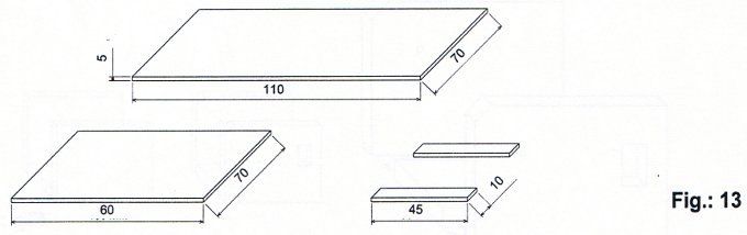
- 3.2.5 Cut the following pieces from the 250 x 70 x 5 mm piece of plywood. 1 piece of 110 x 70 x 5 mm 1 piece of 60 x 70 x 5 mm 2 pieces of 10 x 45 x 5 mm
 3.2.6 Stick the above pieces down in the positions shown in figure 14
 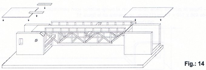 3.2.7 With the flat file , level out the area between the walkway and the 110 x 70x 5 mm piece.
 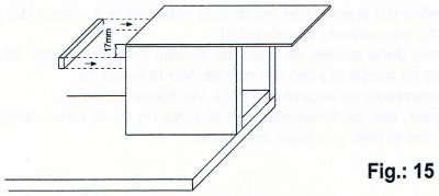 3.2.8 Attach the 70 x 10 x 5 mm strip, obtained in point 3.1.6, as shown in figure 15. The 17mm measurement ought to be checked by supporting the walking on it 3.2.9 Obtain the following pieces from the 325 x 15 x 10mm piece (6) 1 piece of 310 x 15 x 10 mm, 1 piece of 300 x 15 x 10 mm, 1 piece of 160 x 15 x 10 mm 1 piece of 150 x 15 x 10 mm, 2 pieces of 90 x 15 x 10 mm, 3 pieces of 40 x 15 x 10 mm
 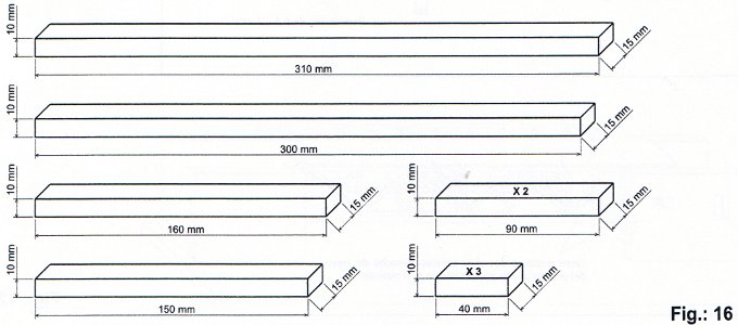 3.2.10 Perforate the 310 x 15 x 10 mm strips and the 300 x 15 x 10 mm strips, obtained in point 3.2.9, as shown in figure17. The holes should be in the upper part arch of the bridge (this will be put together in point 3.2.11). The M4 x 30mm bolts (28) that will form the shaft for winding up the string, will be put through these holes.
 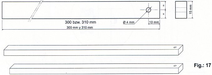 3.2.11 Attach the pieces obtained in point 3.2.10 to the bride supports laterally. The higher arch on the bridge will be formed by a 310 x 15 x 10 mm piece, a 150 x 15 x 100 mm piece and a crosspiece of 90 x 15 x 10 mm.
 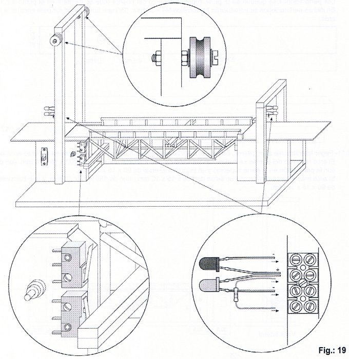 3.2.12 Attach the two wooden pulleys (7) with the M4 bolts (28), four washers (30) and four M4 nuts (29), as shown in figure 9. 3.2.13 Attach the sliding switch in its hole with the 2.2 x 6.5 mm screws (38) and fix the two Limit switches (24) in place, in the positions shown in figure 19, with four 2 x 12 mm screws (37). Note: Firstly, fix the Limit switches in place with one screw and when the rest has been set up, the second screw can be screwed in as we search for the ideal position, in terms of function. 3.2.14 Place the LEDs (21 and 22) and the resistors (23) in the two terminals, as shown in figure 19. Note: The shorter leg of the Led is the negative pole. The polarity of the protective resitors is unimportant. The leg of the resistor mustn’t be in contact with the negative pole of the LED. Fix the connection strip with the LEDs and the resistors to the supports of each arch with a 2 x 12 mm screw (37), as shown in figure 19.
3.3 The construction of the barrier
3.3.1 Draw the shape of the barrier on the 90 x 10 x 5 mm strip of wood obtained in point 3.1.7 and cut it out with the coping saw. See figure 20. Polish up the edge and make a hole of Ø 3mm, as shown. 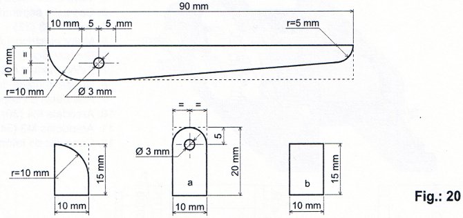 3.3.2 Round off the 20 x 10 x 5 mm piece, as shown in figure 20, and make a hole in it of 3mm. Round off one of the 15 x 10 x 5 mm pieces, as shown in figure 20. The second 15 x 10 x 5 mm piece will form the barrier limit.3.3.3 Put together the four pieces made in point 3.3.1 with a M3 x 20 bolt (32). two M3 washers (34) and two M3 nuts (33), as shown in figure 21. Glue the whole structure to the bridge support.The barrier must be able to move on its access with friction.
 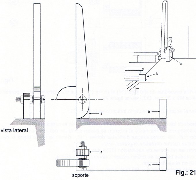 3.3.4 Test the barrier carefully by raising and lowering it manually.3.3.5Attach the rail and the rest of the bars to the sides of the entrance to the bridge. See figures 27 and 28.
3.4 The construction of the reduction motor
In figure 22 we have:
1. Mounting blocks (14) 2. Cylindrical bolt (31) 3. Separating ferrule (15) 4. M3 Nut (33)
5. Electric motor 1.5/4.5V (17) 6. Metal shaft (13) 7. Pinion 0.5 (19) 8. Double toothed wheel, o.5 (18)9. Separating washers (12) 10. M4 washers (30) 11. M3 washers (34) 12. 5mm brass ferrule (16)
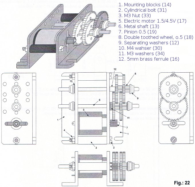 3.4.1 Place the motor and the two separating ferrules (15) between the two mounting squares, fixing them in place with two M3 x 35mm bolts (33). See figure 22.3.4.2 Finish setting up the mechanism, following the directions in figure 22. Start by putting the two shafts (13) in place and passing the separating washers (12) along them. Going from the inside to the outside, pass the 5 M3 washers, the brass ferrule (16) and the four double toothed wheels (18) along the shafts. The last piece should be the red toothed wheel. Check that the toothed wheels interlock well.Finish placing the separating washers (12) on the shafts. All the white toothed wheels should move freely on the shaft.Place the pinion (19) on the shaft of the motor.Only the pinion and the two red toothed wheels are fixed to the shafts.3.4.3 Check the functioning of the motor by moving the pinion of the motor with your hand. The second shaft will be moved by the toothed wheels.
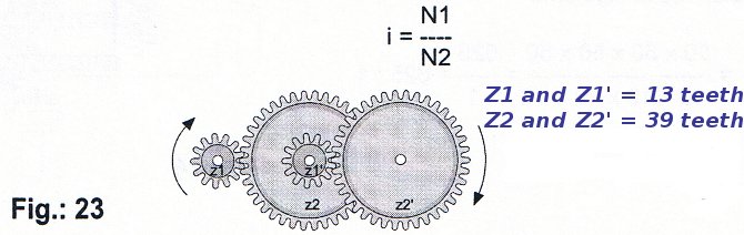
For example, if every time the first wheel turns twice the last wheel turns once, we have the following transmission ratio.
i = N1 / N2 = 2/1 = 2
N1 always represents the entry figure and N2 always represents the exit figure. You can also calculate the transmission ratio working from the number of teeth of on wheel (Z1 and Z2) or from the diameter (D1 and D2):
i = N1 / N2 = Z2/Z1 = D2/D1
When the transmission is a multiplying transmission the exit wheel turns faster than the entry wheel, but with less force. In a non-multiplying transmission the exit wheel turns more slowly but with greater force than the entry wheel. In summary, if the exit wheel turns faster it has less force and if it turns slower it has more force. The intensity of the force is inversely proportional to the velocity of the rotations. When the velocity of the turn reduces by half, the power doubles, if the entry is the same.
brass : any of various metal alloys consisting mainly of copper and zinc