
Note: Once
finished, models shouldn’t be used as toys in the commercial
sense of the word. They are an educational tool, suitable
for the classroom
1.) Technical Information
Activities to be undertaken
Required tools (not included in the
kit)
1.3 Measurements
600x320x150mm
1.4 Objective
The construction of the bridge will allow the students to
learn how to resolve two problems-How to ensure the safe
passage of people and vehicles over the bridge-How to equip
the bridge to allow the passage of boats taller than the
bridge
2.1. Material provided
| Material | Number | Measurements | Piece | Picture |
Plywood |
1 | 10x140x498 mm | Base |  |
| 2 Pine strip | 1 | 10x50x300 | 2x10x50x1002x10x50x50 | |
| 3 Pine strip | 4 | 10x75x80 | ||
| 4 Pine strip | 1 | 10x50x350 | ||
| 5 Plywood | 1 | 5x70x250 | 1x5x70x601x5x70x1102x5x10x45 | |
| 6 Pine strip | 4 | 10x15x325 | 1x10x15x3101x10x15x3001x10x15x160
1x10x15x150 2x10x15x90 3x10x15x40 |
|
| 7 Wooden Pulley | 2 | Ø10×10 mm | ||
| 8 Pine strip | 3 | 5x10x250 | 1x5x10x1151x5x10x903x5x10x80
1x5x10x70 1x5x10x20 3x5x10x15 |
|
| 9 Rods | 12 | Ø3×500 mm | ||
| 10 Cotton thread | 1 | 2 meters | ||
| 11 Metal rod | 1 | Ø3×95 mm | ||
| 12 Retention rings | 6 | Ø3 | ||
| 13 Metal rods | 2 | Ø3 x 70 mm | ||
| 14 Mounting blocks | 2 | 30×53 mm | ||
| 15 PVC fittings | 2 | Ø7 x 25 mm |
Reducing motor | |
| 16 Brass fitting | 1 | Ø4 x 25 mm |
Reducing motor | |
| 17 Motor | 1 | Ø21 x 25 mm |
||
| 18 Double toothed wheel | 4 | 50/10 teeth | 3 whites, 1 red |
2.2 Material provided
| Material | Number | Measurements | Picture |
| 19 Pinion | 1 | 10 teeth |  |
| 20 strips connections | 2 | 12 connections | |
| 21 LED | 2 | Ø 5mm red |
|
| 22 LED | 2 | Ø 5 mm green |
|
| 23 Resistors | 2 | 130 Ω |
|
| 24 Limit switches | 2 | 250 V/5A | |
| 25 Sliding switch | 1 | 6 contacts | |
| 27 Electric wire | 1 | 10 m | |
| 28 screw bolt | 2 | M4 x 30 mm | |
| 29 Nut | 4 | M4 | |
| 30 Washer | 6 | M6 | |
| 31 screw bolt | 2 | M3 x 35 mm | |
| 32 screw bolt | 1 | M3 x 20 mm | |
| 33 Nuts | 4 | M3 | |
| 34 Washer | 8 | M3 | |
| 35 eyebolt | 4 | Ø 3 x 10 mm | |
| 36 Screws | 6 | DIN 7981 | |
| 37 Screw | 8 | DIN 96 | |
| 38 Screw | 2 | DIN 7981 | |
| 39 Battery holder | 1 | 2 (1,5 V) battery | |
| 40 Battery holder connector | 1 |
3. Construction
Before starting to make the bridge it is important to
familiarise yourself with the general plans of the bridge
(figures 27/28) and the diagram of the electrical layout.
Construction phases
3.1. The construction of the moving section of the bridge
3.2 The construction of the bridge
pillars3.3 The construction of the barrier3.4 The
construction of the reduction motor3.5 The assembly of the
different components3.6 Electrical installation
3.1 The construction of the the moving
section of the bridge
3.1.1 Cut two 80 x 50 x 10 mm pieces and two 50 x 50 x 10
mm pieces of wood from the piece of wood measuring 300 x 50
x 10 mm (2), using a saw. The two pieces 80 x 50 x 10 mm are
going to be used for the bridge pillars


3.1.2 Mark the centre of the two 50 x 50 x10 mm pieces,
obtained in point 3.1.1, and round them off as shown in
figure 2. These pieces will serve as the base for the moving
section of the bridge.
3.1.3 Drill a hole through the two pieces at the same,
using a Ø3mm drill piece, at the
point indicated in figure 2.
Note: Put the pieces on on top of the other, fix
them together with adhesive tape and drill both holes at the
same time. The Ø 3 x 95 mm shaft
(11) will be passed through this hole later. 3.1.4 Make a
2.5mm wide and 55mm long groove in both sides of the 10 x 50
x 350 mm strip of wood (4), as shown in figure 3.


3.1.5 Glue the two perforated 50 x 50 x10 mm pieces onto the
walkway piece of the bridge (4), as shown in figure 3. 3.1.6
Cut the following pieces, indicated in figure 4, from the
two large pieces (8) of 500 x 10 x 5 mm. 1 piece of 115 x 10
x 5 mm 1 piece of 90 x 10 x 5 mm 3 pieces of 80 x 10 x 5 mm
1 piece of 70 x 10 x 5 mm 3 pieces of 15 x 10 x 5 mm

3.1.7 Make a slit, 1mm wide and 5mm long, in both ends of
the 115 x 10 x 5 mm piece of wood (obtained in point 3.1.6),
as shown in figure 5.

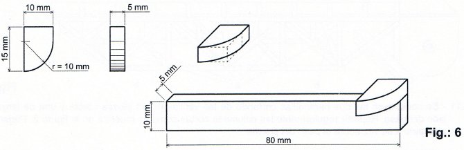
3.1.8 Make a piece like the one shown in figure 6 from
one of the 15 x 10 x 5 mm pieces (obtained in point 3.1.6).
Then glue this piece to the end of a 80 x10 x 5 mm piece of
wood (from point 3.1.6) in the position indicated in figure
6.
3.1.9 Stick the 115 x 10 x 5 mm piece from point 3.1.7,
with the the piece of 80 x 10 x 5 mm, obtained in point
3.1.8, and the 80 x 10 x 5 mm strips onto the walkway of the
bridge, as shown in figure 7. Fix an M4 washer (30) to the
outside face, over the hole, as shown in figure 7.

3.1.10 Make the frame and rails of the walkway of the bridge
using the rods (9) and the template in figure 29, on the
scale 1:1. Make one side first, then the other and glue them
to the underside of the walkway. Then fix the crossbeams (a)
between both frames and the diagonals (b) to each end
triangulating the end of the structures, as shown in figure
8.

3.1.11 Make the two rails by cutting eleven short pieces
and one long piece for each side from the rod (9). Space the
short rods equally, as shown in figure 8. Stick the whole
together and glue to the bridge. Note: Assure
yourself that neither the frame nor the rails exceed the
limits defined in figure 8 as this could cause problems with
the raising and lowering of the bridge.
3.2 The construction of the bridge
supports
3.2.1 With care, cut out a hole in one of the 80 x 75 x
10 mm pieces with a coping saw, as shown in figure 9. This
is where the sliding switch will be placed later, to connect
and disconnect the current. Take a second 80 x 75 x10 mm
piece and bevel the corners of both pieces at the angle
shown and make a hole in the same position in both with a
3mm drill, as shown in figure 9.
Note: Put the two pieces one on top of the other,
join them together with adhesive tape and do the beveling
and perforating in both at the same time.

3.2.2 Stick the two large 80 x 75 x 10 mm pieces with the
Ø 10 mm pieces obtained in point 3.1.1, as shown in figure 10.
Do the same with the two 80 x 75 x 10 mm pieces without
holes and another 75 x 50 x 10 mm piece.

3.2.3 Stick the first piece (the one with holes),
obtained in point 3.2.2, to the large 495 x 140 x 10 mm (1)
piece, to act as a bridge support, as shown in figure 11.

3.2.4 Place the moving part of the bridge (from point 3.1)
between the two bridge supports and fix them in place using
the Ø 3 x 95mm metal shaft (11).
Make sure it can move. On the right, the board must be a
little lower than the horizontal. If necessary, file the
support down a little at the points where it supports the
walkway of the bridge. See figure 12. Fix the rod in place
with the washer (12). See figure 12 Attach the second
support (without holes) to the end of the base. Make sure
there is a gap of 0.5 and 1 mm between the support and the
walkway.

Dictionary:::
pillars: vertical support; a column